|
|
|
Anesthesia Pharmacology Chapter 4: Physics and Anesthesiology
|
|
|
![]()
![]()
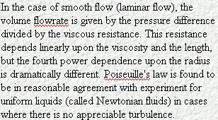
Flow by definition is the quantity of the gas or fluid
which passes a point in unit time. In equation form, F = Q/t where
F is equal to the mean flow,Q = the quantity (mass or volume) and T =
time. The rate of change of a parameter, such as Q, is specified
as Q dot or ![]()
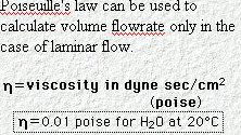
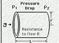
Laminar Flow: [Definition: laminar flow -- "Streamline flow of a fluid in which the fluid moves in layers without fluctuations or turbulence so that successive particles passing the same point have the same velocity. It occurs at low Reynolds numbers, i.e. low velocities, high viscosities, low densities or small dimensions...."45 Laminar flow may be visualized in accord with the diagram below.
Figure above adapted from 46Davis, P.D., Parbrook, G.D, and Kennny, G.N.C. "Fluid Flow", in Basic Physics and Measurement in Anaesthesia, 4th edition, Chapter 2, Butterworth Heinemann, Oxford, 1986.
As noted in the formal definition, laminar flow is characterized by an absence of turbulence and is most likely to occur in smooth "tubes" at low flow rates. We can keep this in mind as we consider gas flow into bronchiolar system as an example of a physiological set of "tubes". In the diagram above the pressure gradient establishes flow direction and interestingly the flow rate is not uniform in the cross-sectional representation. The highest Flow is in the middle of the channel and the flow rate drops to near zero close to the tube wall. For laminar flow, the flow will be directly proportional to pressure and the ratio of pressure to flow defines resistance R, a constant.
46,49Viscosity: Viscosity has to do with shearing forces that occur as "layers" of fluids or gases move relative to each other while flowing.
These shearing forces can be thought of as viscous forces, a type of friction which results in a conversion of flow mechanical energy to heat energy.
Viscosity describes the magnitude of energy loss associated with this type of conversion.
Building on our use earlier of kinetic theory in terms of development though gas laws and pressure-volume-temperature relationships, we can apply kinetic theory in consideration of viscosity also. In the figure above, we note a relatively lower flow rate associated with flows or "lamina" near the edges compared to the center lamina or region. If we start all the way at the edge where the flow is 0 or nearly zero we could imagine that molecules just slightly away from the edge would have a reduction in their momentum as a result of interacting with the nearly stationary "edge" molecules. This reduction is momentum transfer is a process that could repeat between successive lamina as one moves away from the edge and towards the center.
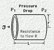
In the figure above consider the pressure drop moving
along the length of the tube (from P1 to P2).
This pressure drop is proportional to viscosity (among other things) as
reflected in the formulation P1 - P2 = 8 [(Q![]() l/
l/![]() r4
)], where Q is the flow rate in m3/sec;
r4
)], where Q is the flow rate in m3/sec; ![]() is the viscosity coefficient, R is the radius, l is the distance between
P1 and P2 . In terms of units, if R & l
are defined in meters and the pressure in Pascals (Pa) then the units of
viscosity is pascal-second (Pa*s)
is the viscosity coefficient, R is the radius, l is the distance between
P1 and P2 . In terms of units, if R & l
are defined in meters and the pressure in Pascals (Pa) then the units of
viscosity is pascal-second (Pa*s)
49As flows in different lamina move relative to each other there is a dynamic sheer stress associated with this process.
![]() symbolizes dynamic sheer stress which is proportional to velocity
differences between fluid lamina layers.
symbolizes dynamic sheer stress which is proportional to velocity
differences between fluid lamina layers.
These velocity differences are defined in terms of unit distance between the layers and is called a velocity gradient.
Such
a velocity gradient then would be the slope of a graph which plots
velocity differences between layers as a function of the distance
between layers. Shearing stress divided by the rate of shearing
strain is defined as dynamic viscosity or ![]() .
.
49In this model, the velocity of flows is uniform within a lamina, i.e. no turbulence and this condition of smooth flow is called laminar flow. Furthermore, one may graph velocity of the lamina as a function of distance and this graph describes a velocity distribution. For laminar flow, the graph would be a straight line in which the slope of the line is called the velocity gradient. If we were to consider a set of lamina such that U would represent the edge and H would represent the surface of the "upper" lamina, then the slope that we referred to earlier would be U/H.
Dynamic viscosity in terms of the above
relationships would be ![]() =
=
![]() /(U/H).
/(U/H).
The shearing stress, ![]() ,
may also be thought of as a force applied over the area of the
lamina, A, such that the above equation can be written
,
may also be thought of as a force applied over the area of the
lamina, A, such that the above equation can be written ![]() =
(F/A) / (U/H)
=
(F/A) / (U/H)
In our laminar flow example, the velocity distribution from lamina to laminar (laminar plate to laminar plate) was linear and therefore the velocity gradient would be constant throughout the fluid.
However, if the velocity distribution was not linear then the velocity gradient would have to be expressed as a slope of the velocity distribution at the particular point in question, which would be derivative at that point or du/dh.
At
that particular point then the stress between two layers is given by
![]() =
= ![]() * du/dh. This final equation indicates that if the relationship
between the sheer stress,
* du/dh. This final equation indicates that if the relationship
between the sheer stress,![]() and the velocity gradient du/dh is linear then the slope,
and the velocity gradient du/dh is linear then the slope,![]() ,
is a constant.
,
is a constant.
Under these conditions, dynamic viscosity (![]() )
would be a fluid property and those fluids which exhibit constancy
in dynamic viscosity are called Newtonian fluids. Blood,
however, is an example of a fluid in which a nonlinear relationship
exists between sheer stress and the velocity gradient; accordingly,
blood is a non-Newtonian fluid.
)
would be a fluid property and those fluids which exhibit constancy
in dynamic viscosity are called Newtonian fluids. Blood,
however, is an example of a fluid in which a nonlinear relationship
exists between sheer stress and the velocity gradient; accordingly,
blood is a non-Newtonian fluid.
Dynamic viscosity units are Pa * s, which can be
determined from the equation ![]() =
=
![]() /(U/H)
by substituting in units as we go along; therefore,
/(U/H)
by substituting in units as we go along; therefore,![]() =
=
![]() /(U/H)
= (N/m2) / (m/s / m) = (N * s) /m2
= Pa * s (pascal-second).
/(U/H)
= (N/m2) / (m/s / m) = (N * s) /m2
= Pa * s (pascal-second).
Examples of some viscosities:
air:[20oC], 0.018 10-3 Pa*s
water: [40oC], 0.653 10-3 Pa*s
water: [20oC], 1.003 10-3 Pa*s
castor oil: [20oC], 986 10-3 Pa*s
glycerin: [20oC], 1490 10-3 Pa*s
Dynamic viscosity dependencies:
Gases -- dynamic viscosity exhibits temperature dependencies; with increasing temperature for gases, dynamic viscosity increases.
The explanation, from kinetic theory would be that with the higher kinetic energy distributions there is an increase in gas interactions between lamina.
This increase in interaction is consistent with an increase in friction and therefore an increase in the apparent dynamic viscosity.
Liquids: interactions between molecules in the liquid tend to be characterized by relatively weak bonds which are easily disrupted by increasing the kinetic energy (temperature) of the system.
Accordingly, it would be expected that for liquids dynamic viscosity would decrease as the kinetic energy of the system (temperature) increases.
Kinematic Viscosity:
Kinematic viscosity is defined as a ratio between dynamic viscosity
and density (![]() =
= ![]() /
/ ![]() ), where
), where
![]() is kinematic viscosity,
is kinematic viscosity, ![]() is dynamic viscosity and
is dynamic viscosity and ![]() is density.
is density.
The units for kinematic viscosity are m2/s.[![]() = [(N * s) /m2 ] / kg/m3 = kg * m * s/m2
/ kg/m3 ]
= [(N * s) /m2 ] / kg/m3 = kg * m * s/m2
/ kg/m3 ]
![]()
47Again, consider the equation P1 - P2 = 8 [(Q
l/
r4 )], where Q is the flow rate in m3/sec;
Let's apply this equation to an example in hemodynamics, specifically a case in which we suppose that the average arterial diameter is amount 0.1 mm and that this diameter is regulated in accord with the vasomotor tone.
The question is by what amount the arterial would have to contract in order to reduce the blood flow to 20% of the initial value (assuming constant pressure drop)
We will use subscripts to describe the initial condition (subscript 1) in the constricted state (subscript 2). In terms of the equations we would have: 8 [(Q1
Therefore the arterial has constricted to about 67% of the initial diameter; so with the initial diameter being about 0.1 mm, following constriction the diameter is about 0.67 mm.
A couple of other points: when dealing with blood vessels generally the problem is a little more complicated because of the compliance of the vessel wall allowing distention at higher pressures (by comparison to a glass tube, for example).
Also, the viscosity of whole blood decreases significantly at the level of the capillary (a decrease of about 50%) possibly due to the registration of the blood cells as they pass one at a time through the capillary.
|
|
Figure above adapted from Reference 49
As suggested above, flows may be laminar in which fluids move in thin layers or turbulence reflecting irregular motion with the velocity fluctuations.
These fluctuations are superimposed on the underlying regular (average) flow.
A question arises concerning what factors predisposed to relatively laminar vs. turbulent flow behavior.
If the example we use would be movement of your hand through the liquid and if the movement is slow, you will become aware of a moderate resistance to movement.
The two components responsible for resistance is (a) an inertial resistance to the acceleration of the water that your hand is displacing and (b) a viscous drag force.
The interplay between these forces sometimes described as forces due to momentum and forces due to viscous friction ultimately determine if the flow is laminar or turbulent.
One mathematical formulation for the Reynolds number (there are several formulas that are essentially equivalent) is given below:
Reynolds number = (v
d) /
Generally, Reynolds numbers less than about 2000 correspond to laminar flow, whereas Reynolds number is greater than about 3000 characterize turbulent flow.
Reynolds numbers between 2000 and 3000 reflect unstable flow that can transition between laminar and turbulent characteristics.
Recalling that the Reynolds number is a ratio of inertia forces (momentum) to viscous forces, smaller Reynolds numbers are consistent with relatively larger viscous forces which would predispose to laminar flow. Larger Reynolds numbers then indicate dominance of momentum forces which predispose to turbulence. As we will discuss in our consideration of the equation of continuity below, a narrowing of a tube containing a flowing liquid will be associated with an increase in velocity in that narrowed region compared to the bulk volume.
|
|
An important clinical consideration has to do with a change in the relationship between flow and pressure as flow transitions from laminar to turbulent.
In particular, for turbulence flow inside pathways that have rough internal edges, flow appears about proportional to the square root of pressure or a doubling of flow requires a quadrupling of pressure.
Furthermore, with turbulent flow, since pressure to flow relationships do not exhibit linearity, resistance will not be constant.
In the turbulent flow case, resistance measurements must be specified in terms of the particular flow rate.
Physiologically, during breathing, airflow resistance will depend on the air flow rate assuming turbulence.
For turbulent flow, a nonlinear relationship exists between flow and pressure as shown below:
Relationships between flow and pressure: (laminar)
The relationship above illustrates that Pressure is
proportional (![]() )
to Flow [ P
)
to Flow [ P ![]()
![]() ]
and P/
]
and P/![]() =
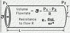
R, where R represents the resistance of the tube.
=
R, where R represents the resistance of the tube.
The resistance can be measured using an approach described in the figure below: [Figure below adapted from 46Davis, P.D., Parbrook, G.D, and Kennny, G.N.C. "Fluid Flow", in Basic Physics and Measurement in Anaesthesia, 4th edition, Chapter 2, Butterworth Heinemann, Oxford, 1986. ]

The above figure is analagous to the fixed restrictor part of a desflurane vaporizer design:
![]()
If the flow is constant, i.e. ![]() is constant then the magnitude of the resistance caused by the
constriction can be determined from P1 and P2.
The resistance would be (P1-P2)/
is constant then the magnitude of the resistance caused by the
constriction can be determined from P1 and P2.
The resistance would be (P1-P2)/![]() =
R.
=
R.
![]() The fourth power dependency of radius (or diameter)
is illustrated below: [Figure below adaptedfrom 46Davis,
P.D., Parbrook, G.D, and Kennny, G.N.C. "Fluid Flow", in Basic
Physics and Measurement in Anaesthesia, 4th edition, Chapter 2, Butterworth
Heinemann, Oxford, 1986. ]
The fourth power dependency of radius (or diameter)
is illustrated below: [Figure below adaptedfrom 46Davis,
P.D., Parbrook, G.D, and Kennny, G.N.C. "Fluid Flow", in Basic
Physics and Measurement in Anaesthesia, 4th edition, Chapter 2, Butterworth
Heinemann, Oxford, 1986. ]

In the figure above note that the only difference is a
change in the tube diameter from 1d to 1/2d, but this change alters the flow
rate, ![]() ,
from 1Q to 1/16 Q, a fourth power effect (1/2 x 1/2 x 1/2 x 1/2 = 1/16).
,
from 1Q to 1/16 Q, a fourth power effect (1/2 x 1/2 x 1/2 x 1/2 = 1/16).
Small changes in the diameter of an endotrachial tube would have large effects on flow, assuming constant pressure.
Hemodynamically, changes in vasomotor tone, causing vasoconstriction, have similar large effects.
|
|
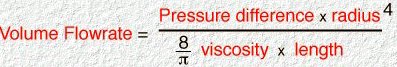
The equation
=
Now, using an example provided by Rod Nave, Ph.D., consider the case in which the areas the need for a significant increase in blood volume flow rate in a so-called "flight or flight" situation.
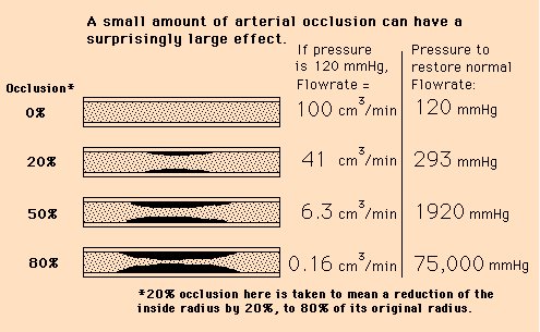
If a 5-fold increase in blood flow were required in this could be accomplished only by increasing blood pressure, then the pressure would have to be increased from a nominal 120 mm Hg to 600 mm Hg, a clearly impossible physiological response.
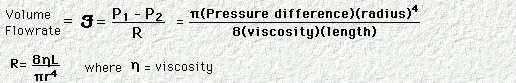
By contrast, vasodilation of only 50% is sufficient to accomplish the fivefold increase in flow. Note in the equation above the fourth-power dependency of diameter (or radius); so, going from 1r to 1.5r would provide (1.5)4 or 5.06 increase in volume flow rate. Furthermore, a 50% vasodilation is physiologically reasonable.
Factors that are important in this system include, the flow
rate, ![]() ,
pressure across the tube, tube diameter, d, tube length, l, and fluid
viscosity.
,
pressure across the tube, tube diameter, d, tube length, l, and fluid
viscosity.![]() and the relationship that summarizes these factors has the form
and the relationship that summarizes these factors has the form ![]() =
=
![]() Pd4
/ (128
Pd4
/ (128![]() l ) [Hagen-Poiseulle equation] which may also be
written to highlight pressure dependencies as: P = (128
l ) [Hagen-Poiseulle equation] which may also be
written to highlight pressure dependencies as: P = (128![]() l
l ![]() )
/
)
/ ![]() d4
d4
The figures and Poiseuille's Law material below, courtesy of Dr. Rod Nave, Georgia State University
|
|
|
|
|
|
|
|
|
|
![]()
Laminar flow: "equation of continuity":
If one imagines a hose of a particular diameter and with a particular flow rate going through the first part of the hose, for example two liters per second and then one looks at the end of the hose and finds not unexpectedly a flow rate coming out of also two liters per second.
Looking in the middle one finds the region of constriction such that the diameter is less than the diameter of the hose of the first part or last part and we looked at earlier.
The only way we can insure that the rate of flow coming out the end with the larger diameter is the same as the rate can we start with in the beginning part of the hose is to guess that the flow through the constructed region must be faster given the reduction in diameter in that region.
Technically this analysis applies to laminar flows of an incompressible fluid and an equation to represent this relationship would be as follows:
![]() A1v1
A1v1![]() t
=
t
= ![]() A2v2
A2v2![]() t
where
t
where ![]() is the density and A represents the areas and v the velocities.
Consider the graphical representation of the equation below: (Adapted
from 47Jones, E.R. and Childers, R.L, "Fluids"in
Contemporary College Physics Addison-Wesley, Reading, Massachusetts,
1993, p 281 (figure 10.18)
is the density and A represents the areas and v the velocities.
Consider the graphical representation of the equation below: (Adapted
from 47Jones, E.R. and Childers, R.L, "Fluids"in
Contemporary College Physics Addison-Wesley, Reading, Massachusetts,
1993, p 281 (figure 10.18)
47A1 represents the area (cross-sectional)
corresponding to the larger diameter in the hose example above with the
volume of fluid flowing across A1 in the time interval ![]() t
represented by
t
represented by![]() V1
which is equal to A1v1
V1
which is equal to A1v1![]() t.
Similarly, the mass of fluid would the equal to the density
t.
Similarly, the mass of fluid would the equal to the density ![]() x A1v1
x A1v1![]() t
The mass of fluid flowing out of the tube at A2 in the same
time period
t
The mass of fluid flowing out of the tube at A2 in the same
time period ![]() t
would be
t
would be ![]() x A2v2
x A2v2![]() t.
The density value,
t.
The density value,![]() ,
can be dropped from the equation because of the assumption of
incompressibility, leaving the "equation of continuity", v1A1
= v2A2. Since the flow of
mass through the system remains constant but we have changed the
cross-sectional area, the velocity values must compensate in the
opposite direction. So any region of constriction, with reduced
cross-sectional area, the velocity, i.e. the rate of movement of mass
through that cross-sectional area must increase. This finding is
necessary for the system to remain in accord with the principle of conservation
of mass.
,
can be dropped from the equation because of the assumption of
incompressibility, leaving the "equation of continuity", v1A1
= v2A2. Since the flow of
mass through the system remains constant but we have changed the
cross-sectional area, the velocity values must compensate in the
opposite direction. So any region of constriction, with reduced
cross-sectional area, the velocity, i.e. the rate of movement of mass
through that cross-sectional area must increase. This finding is
necessary for the system to remain in accord with the principle of conservation
of mass.
47The conservation of mass is a primary idea in physics and is thought of along with conservation of momentum and conservation of energy. Our example is really one of fluid dynamics in which we are looking at the amount of fluid passing through a certain point within a certain amount of time. For example if we know the area at that point, e.g. A and the fluid passes through at velocity V than the volume would be A * V * T or A * length/time x time [length/time is velocity] or A * length = volume.
In our system, the density is constant, therefore because of the conservation of mass, in the velocity is known at some cross-sectional area then velocity can be calculated for any other cross-sectional area.
If the cross-sectional area is reduced, the velocity is increased. That circumstance is the example shown below in which the area "b" is 50% of the area "a". Inspection of the results indicate that in order to conserve mass the "b" system velocity is 2x the "a" system velocity.
The overall quantity
under consideration is density (![]() )
x area x velocity which has the dimensions of mass/time and is
referred to as mass flow rate. [Animation attribution: 48Tom
Bergson, Conservation of Mass, Glenn Research Center, NASA, http://www.grc.nasa.gov/WWW/K-12/airplane/mass.html)
)
x area x velocity which has the dimensions of mass/time and is
referred to as mass flow rate. [Animation attribution: 48Tom
Bergson, Conservation of Mass, Glenn Research Center, NASA, http://www.grc.nasa.gov/WWW/K-12/airplane/mass.html)
|
|
The above is a problem in fluid dynamics and can be contrasted with solid mechanics and fluid statics (see below)48
|
|
47Example of an application using the "equation of continuity", v1A1 = v2A2
A horizontal tube of 15 cm2 cross-sectional area carries water with the velocity of 2m/sec.
This tube connects to a smaller pipe which has a cross-sectional area of 5 cm2 .
Calculate the velocity of the water in the smaller pipe.
We begin with the equation of continuity, v1A1 = v2A2 rearranged so that we can solve for v2 or v2 = (v1A1)/A2 .
Substituting we have v2 = (2m/sec * 15 cm2 )/5 cm2 or 6m/sec
Bernoulli's theorem: P1 + 1/2 ![]() v12
= P2 + 1/2
v12
= P2 + 1/2 ![]() v22
where v = flow velocity, P = pressure and
v22
where v = flow velocity, P = pressure and ![]() = density. (this form is for a
horizonal "tube" such that gravitational contributions may be
omitted)
= density. (this form is for a
horizonal "tube" such that gravitational contributions may be
omitted)
Also, A1v1=A2v2 where A is the circular cross-sectional area and v = flow velocity
The figure and Bernoulli material below, courtesy of Dr. Rod Nave, Georgia State University, illustrates Bernoulli's equation in complete form.
|
![]()
|
|
|
|
![]()
46Davis, P.D., Parbrook, G.D, and Kennny, G.N.C. "Fluid Flow", in Basic Physics and Measurement in Anaesthesia, 4th edition, Chapter 2, Butterworth Heinemann, Oxford, 1986.
47Jones, E.R. and Childers, R.L, "Fluids"in Contemporary College Physics Addison-Wesley, Reading, Massachusetts, 1993, p 281.
48Tom Bergson, Conservation of Mass, Glenn Research Center, NASA, http://www.grc.nasa.gov/WWW/K-12/airplane/mass.html)
49Duffin, J, "Fluid Mechanics" in Physics for Anesthetists, Charles C. Thomas, Springfield, IL., 1976, 144-151.